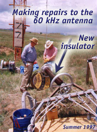
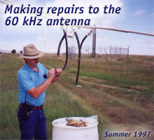
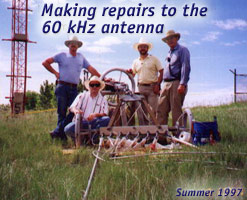
The antenna. The antenna for WWVB undergoes regular maintenance, as well as periodic upgrades. These photos were taken during a major upgrade which took place from 1997 to 2000.
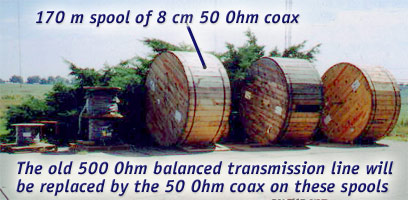
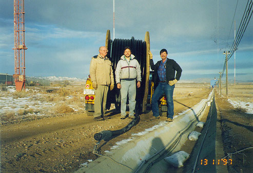
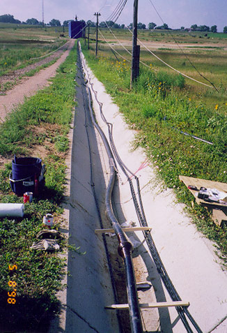
The transmission line. A 50 Ohm transmission line connects the 60 kHz transmitter in the broadcast house with the antenna. The transmission line begins on huge spools, and is buried in a shallow trench.
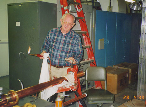
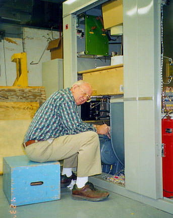
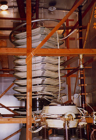
Variometer installation. With the 60 kHz antenna, the transmission line must be matched to the antenna though a coil called a variometer.
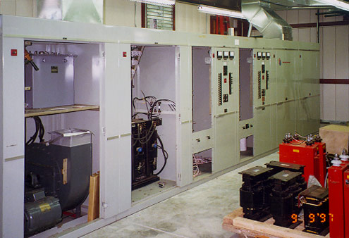
New equipment. Construction of the new 60
kHz transmitters.
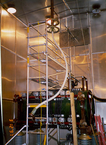
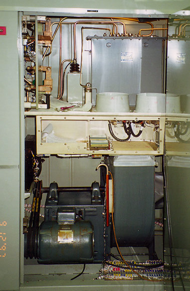
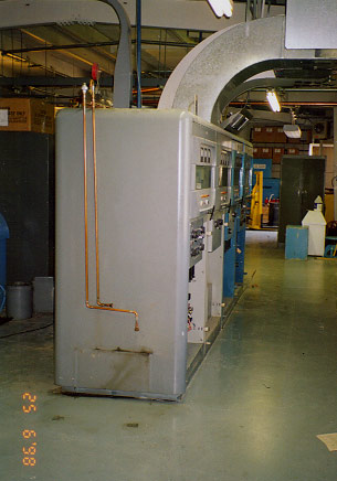
Retired equipment. The following are the old 60 kHz transmitters and antenna matching transformer.
|