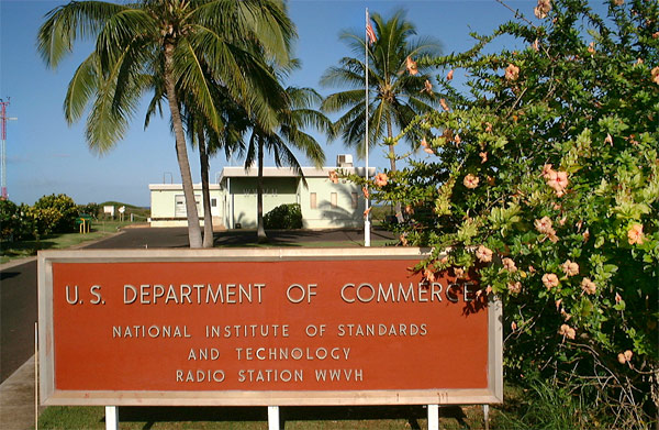
The station's surroundings. After serving the Pacific area for 23 years from the Island of Maui, Hawaii, Radio Station WWVH was relocated to the western edge of the Island of Kauai, Hawaii in 1971. The facility is located near Kekaha at Kokole Point. Around the clock, continuous broadcast services from Hawaii supplement those from WWV in Fort Collins, Colorado, by providing coverage in the Pacific Basin.
| Entrance |
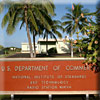 |
| Station entrance to WWVH in Barking Sands, Kauai |
|
 |
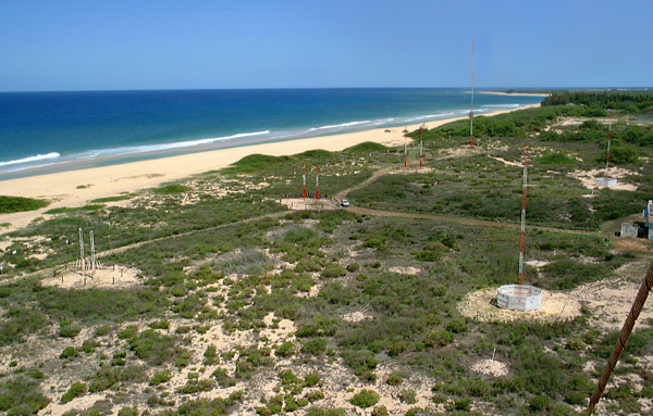
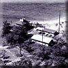
| Sunset |
 |
| View from WWVH, Niihau Island on left horizon |
|
|
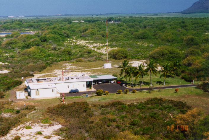
| Station house |
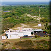 |
WWVH in Barking Sands, Kauai
In the foreground is the weather instrument tower, in background, standby 2.5 MHz monopole |
|
|
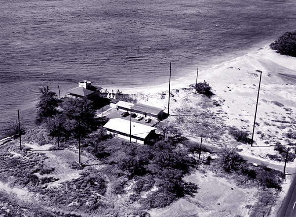
| Old Station |
 |
WWVH in Kihei, Maui 1948 to 1971.
Antennas left to right: 10.0 MHz, 5.0 MHz, Reception, 15.0 MHz, and 2.5 MHz
Buildings left to right: Office, transmitter, generator & shop |
|
Clocks & antennas. Several cesium atomic clocks provide the precise timing information broadcast by WWVH, these signals are amplified by transmitters (below) and broadcast from several antennas. Three atomic frequency standards at WWVH provide optimum timekeeping ability. These "atomic clocks" are kept in as close agreement as possible with the UTC(NIST) time scale located in Boulder, Colorado.
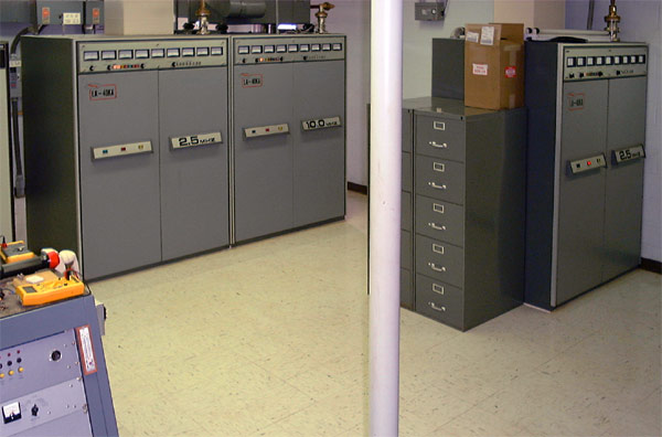
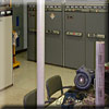
Transmitters. These transmitters amplify the time signal that is sent to the antennas.
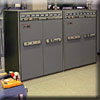
| Left view |
 |
| Transmitters from left to right: Primary 5.0 MHz (10kW), Standby 5.0 MHz (5kW), and Standby 15.0 MHz (5kW) |
|
|
| Center view |
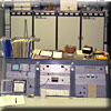 |
Transmitters from left to right: Standby 15.0 MHz (5kW), Primary 10.0 MHz (10kW), and Primary 15.0 MHz (10kW)
Console panels left to right: oscope and multi-channel recorder; modulation, carrier and master control for transmitters; and station status,
RF exiters and audio amplifiers |
|
|
| Right view |
 |
| Transmitters from left to right: Primary 2.5 MHz (5kW), Standby 10.0 MHz (5kW) and Standby 2.5 MHz (5kW) |
|
|
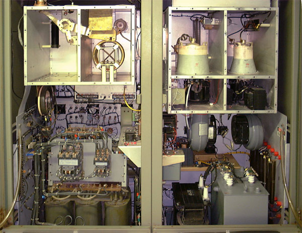
| 10,000 Watt |
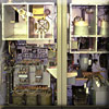 |
WWVH Typical Interior of a 10000 Watt Class C Plate Modulated Transmitter
Top left: Final tuning circuit
Top right: PA and modulator tubes
Bottom Left: High voltage power supply, control panel
Bottom Right: Modulator transformer, screen power and choke |
|
At WWVH, only one clock is "on the air" at any time. The other two permit clock comparison and emergency or standby service. Satellite synchronization methods are used to keep WWVH clocks "in step" with NIST/Boulder standards.
A time code generator allows recorded voices and special announcements to be programmed automatically into the broadcast format. This information provides modulation through a synthesizer for the four standard broadcast frequencies. A female voice announces WWVH's time, thus allowing distinction from WWV's male voice. The RF signals are amplified through high power transmitters and fed to the antenna systems. The antennas are modified half-wave dipole phased arrays with the exception of the 2.5 MHz and standby monopoles.
|